5.2.5 Georeference vector map - LUPMISManual
Main menu:
5.2.5 Georeference Vector Map
Level of expertise required for this Chapter: Expert; general Map Maker training
This is a ‘long-and-dirty’ method, and should be used only, if all other georeferencing options fail.
In exceptional cases there might be a need to georeference a vector map, which has been digitized in an unknown or undefined projection, or without any projection references at all, for example, maps, which have been created in a graphics program, very often also maps drawn in AutoCAD (see also Chapter 5.4.3 for the procedure to import GIS data from AutoCAD). These maps can be georeferenced in a crude way in UTM with following procedure.
Only a linear rectification can be performed. Therefore, the best results will be if the source map is in TM, UTM or similar projection (War Office is ok, latitude / longitude is not ok) and covers only a small area (max. 10 km).
1. Identify two ground control points on the map, preferably close to the NW corner, the other to the SW corner.
2. Load the map (with its ‘wrong’ projection) into Map Maker and measure the distance on the map, as displayed in Map Maker with the Tape-tool from the toolbar left.
Alternatively, you can use the formula SQRT ( (xNE – xSW)2 + (yNW – ySE)2 ).
3. Load a map with correct georeference (GPS-tracked, georeferenced photo or similar) and measure the true distance on ground.
Alternatively, you can use the same formula as above.
4. Divide the figure of step 2 by the figure of step 3. This will give the multiplication factor. If it is > 0, the map will be enlarged, if it is < 0, it will be reduced.
5. Apply the multiplication factor: Main menu > Utilities > Vector utilities > Actions > Select folder and file to be referenced > Transform window: Transformations > Multiply coordinates of vectors > OK > Stretch coordinates window: x = 0 > y = 0 > Enter Multiply by: Multiplication factor of step 4 above >
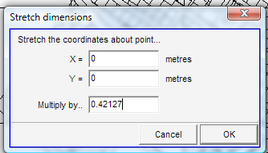
> Specify new file name > Save
6. Display the new map and check the distance between the two points, to see if it is equal to step 3.
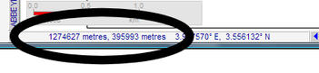
7. Read the ‘false’ xy coordinates of the 1 ground control point (GCP). (For example, you can take the Map Maker coordinates, which are shown at the bottom left).
8. Get the true xy coordinates of the same point (1. GCP), either from GPS-tracked data or correct layer in the GIS.
9. Calculate the difference both for x and for y (the distance to shift). Consider carefully, if it is a positive or negative shift.
10. Shift the map to match the 1. GCP: Main menu > Utilities > Vector utilities > Actions > Select folder and file to be referenced > Transform window: Transformations > Shift coordinates of vectors > OK > Shift coordinates window: Enter x and y value from step 9 above > OK >
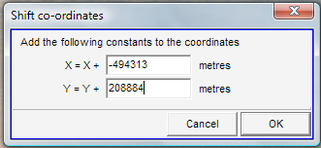
> Specify new file name > Save
11. Display the new map and see, if the 1st GCP matches. If not, repeat steps 7-10.
12. Check for the 2nd ground control point. If the map was in the correct north orientation, the point of the map matches the location on the ground. In this case, the procedure is completed. Otherwise, the map has to be rotated:
13. Main menu > File > System set up > Preferences > Set up window: Preferences > Miscellaneous > Tick ‘Decimal degrees for angles’ > OK
14. Read the angle to the ‘false’ 2. GCP by drawing a line (dragging the mouse) from the 1. GCP to the 2.GPC, as shown on the map (‘false’ 2. GCP) and read the angle: Right-mouse > Measurement > Angle measurer
15. Read the angle to the true 2. GCP in the same way.
16. Calculate the difference between the values of step 14 and step 15. Consider carefully, if it should be a clockwise rotation (positive) or anticlockwise (negative).
17. Rotate the map: Main menu > Utilities > Vector utilities > Actions > Select folder and file to be referenced > Transform window: Transformations > Rotate coordinates of vectors > OK > Revolve coordinates window: x = x value of 1. GCP > y = y value of 1. GCP > Revolve by: Enter calculated figure of step 16 > OK
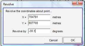
> Specify new file name > Save
18. Load the map and check the two ground control points. They should fit to the predefined locations. If not, repeat the steps before.
19. Have a thorough look at the entire map and see, if all matches with the other background map layer or images.
- - - - -
Note 1: If majority of the map is ok, but only a part of it appears wrong, you might have to consider the tool of vector rubber sheet (Main menu > Edit > Live layer rubber sheet > Show vector rubber sheet, which is explained in a separate Chapter).
- - - - -
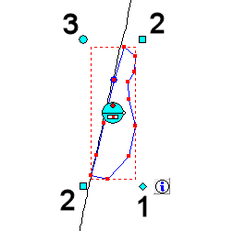
Note 2: If there is only one feature to be georeferenced, you can choose a faster approach by processing steps 7-11 above and then stretch it in the live layer:
In live layer > Edit-tool (at toolbar left) > Double-click on the unit >
Bottom right, diamond (1, see below): to move (see end of Chapter 3.9
Bottom left or top right, square (2): to stretch
Top left, circle (3): revolve / turn