7.4.3 GIS process for Framework - LUPMISManual
Main menu:
7.4.3 GIS Process for Framework
Level of expertise required for this Chapter: Intermediate; specifically for LUPMIS @ TCPD
Before you start, load the classification (classes) for the Framework (style library Framework_tl, see Annex 6.2).
- - - - -
1. For urban settlement schemes, calculate the future, planned population, living in each community considered under the Framework.
See Annex 15 for statistics and examples on population projections and planned population forecasts. Growth rates are very difficult to estimate.
For example, a population forecast table can look like the one below.
These figures will also be used for land requirement calculations ( step 5.4 of Chapter 7.5.2 and 0 of lt Chapter 7.5.3).
- - - - -
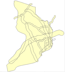
2. Draw major roads, either current or future (planned).
- - - - -
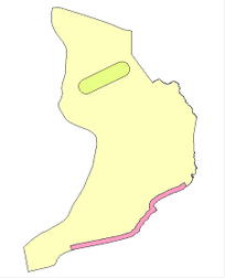
3. Draw exclusion zones or special development areas.
These can be nature reserves, habitats, tourism development areas, mining areas or similar.
Take these areas (received during the preparation) and draw them in very general terms. Often, they will be buffers or have the shape of crude squares or rectangles. (Example below shows nature reserve and tourism development areas).
- - - - -
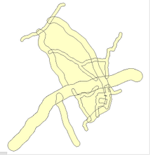
4. Draw development corridors along the roads digitized in step 2 above in 1-3 hierarchical levels.
- 4.1 Remove segments smaller than 100 m: In live layer: Main menu > Edit > Show Selection Manager > Select-tool (at toolbar left) > Select all digitized roads to be buffered > Selection Manager window: Actions > Tidying > Remove segments smaller than > Remove segments smaller than window: 100 (might be upto 500) > OK
- 4.2 For each line of the 1st priority planning corridor: Buffer with 1500 m (This might vary from one Framework to another): Still in live layer, with roads selected > Selection Manager window: Actions > Polygon manipulation > Generate buffer zones > Generate buffer zone window: Width of buffer zone: 1500 > Number of buffer zones: 1 > Tick ‘Generate as polygons’ > Untick ‘Keep original objects’ > Orientation of zone: External buffer > OK >
If many roads were buffered, the result might not be ok. In such a case, take less roads, and repeat.
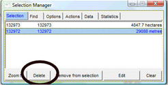
Selection Manager window: Selection: There should be no line (i.e. unit with metres), and no units of very small area (0.0 or 0.1 hectares). If there are, select and delete them.
‘Clean’ the buffer: Selection Manager window: Tidy > Tidy polygon topology > Selection Manager window: Remove segments smaller than > Remove segments smaller than window: 500 > OK
Save under temporary filename.
- 4.3 For all lines of the 2nd priority planning corridor: Buffer with 800 m (This might vary from one Framework to another). Repeat all steps of 4.2.
- 4.4 You might consider a 3rd priority planning corridor: Buffer with 400 m (This might vary from one Framework to another). Repeat all steps of 4.2.
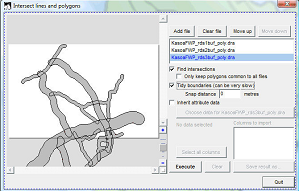
- 4.5 Combine all these buffers into one layer: Main menu > Utilities > Vector utilities > Intersect/Unite files > Intersect lines and polygons window: Add file > Select folder and all files, which you just created > Tick ‘Find intersections’ > Tick ‘Tidy boundaries’ > Execute > Save result as …. > Select folder and give new temporary filename > OK > Quit
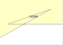
This file, which you just created, might have to be ‘cleaned’ by ‘joining’ and ‘deleting’ small units.
Such a ‘sliver’ has to be ‘joined’ to the larger unit:
- 4.6 Next, you assign styles (recommended: 1-3) to these buffers.
- - - - -
<a name="Step5"></a>
5. Define the centres (‘nodes’) of existing or future development and investments
With background maps (topography, existing settlements, roads) and the previously developed development corridor map, you can draw approximate centres as points (‘symbols’). See Annex 6.2 for proposed classes.
These can be town centres, which already exist and should be expanded both in size and in functionality. Or, they can be small settlements or tiny business aggregations to be supported. Or, they can be completely new hubs for development.
Be aware, that these development centres do not necessarily have all the same function. One can be an industrial hub, while another one can be solely for residential purposes with shopping centres, administration and service function. This is to be specified by the planner, following the directives given in the Medium Term Development Plan.
- - - - -
6. Form circles (‘buffers’) around these centres
This will help both to demonstrate and to give a first spatial requirement. The colour of these round buffers (circles) should indicate the functionality, the size gives an impression of the area, importance or population.
These circles do not describe the actual spatial pattern, only a rough approximation, which has to be delineated in detail at the Structure Plan.
It will also help to assign areas, which are not to be developed for various reasons (ecologically sensitive, ‘green belt’, protection zone, farmland etc).
- 6.1 Create buffers: Have the node layer of the previous step in live layer mode > Main menu > Edit > Show Selection Manager > Select-tool (at toolbar left) > Select point (node) > Selection Manager window: Actions > Polygon manipulation > Generate buffer zones > Generate buffer zone window: Width of buffer zone: Enter the distance expressed in meters (between 200 and 5000 m) > Number of buffer zones: 1 > Tick ‘Generate as polygons’ > Tick ‘Keep original objects’ > Orientation of zone: External buffer > OK
After all buffers are created, check that no points (nodes, ‘symbols’) remain in your polygon layer. Otherwise, delete them (Main menu > Edit > Select all > Show Selection Manager > Selection Manager window: Features, which do not have ha or km2: Delete).
- 6.2 In many cases, these circles will overlap. Repeat the process ‘Combine all these buffers into one layer’ explained in step 4.5 above to ‘unite’ them.
After processing it might be necessary to ‘join’ these buffers.
- 6.3 Assign functionalities (‘styles’) to these round buffer zones. See Annex 6.2 for units.
- - - - -
7. It is a good practice to have a few location names (names of towns or villages) placed on the map.
- - - - -
8. Development characteristics, such as number of population to move to this area, schools, infrastructure etc should now be placed as labels (without point) to the map.
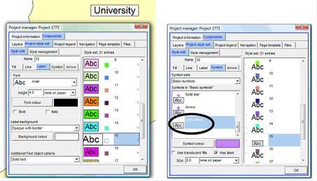
You can insert them with the Text-tool from the toolbar left. If there are any problems, you can also define points (with the Symbol-tool), enter the text for display, and choose size, font, background of the label, and ‘Just a label’ under the Symbol tab.
- - - - -
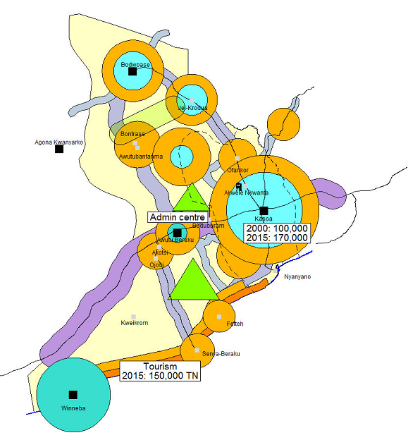
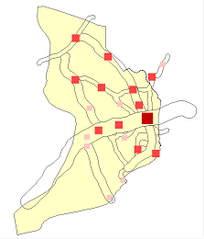
9. Save
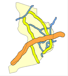
The sample map below demonstrates the basic features of a Framework, here of the Awutu district. The actual Framework of this area considers more input parameters, is considerably larger and more complex, and has marginalia and legend (see Chapter 7.4.4).