A2.4 Process of orthophoto map production - LUPMISManual
Main menu:
A2.4 Process of Orthophoto Map Production
Level of expertise required for this Chapter: Intermediate; general GIS training
The process of producing orthophoto maps passes through different stages:
A) Aerial photography
Photos are taken by a camera from an airplane. There are different technologies to take these photographs. It can be done either from low-altitude (recommended) or high-altitude (conventional, because of cloud cover in Ghana less recommended) flying airplanes.
These can be done with digital cameras (recommended, as this is fast, precise, economic) or on conventional films (which have to be chemically developed and then scanned, because of these processes and the time required less recommended).
The output of this process are aerial photos in digital format (mostly, in TIF format).
- - - - -
B) Georeference
The photos have to be georeferenced, i.e. with general reference to the location, often positioned either on the centre of the photo or on a few points.
The output of this process are georeferenced photos, with coordinates either embedded in the photo file (for example, GeoTIFF file) or added as a separate 'world file' (JPW for JPG, TFW for TIF, BMW for BMP).
- - - - -
C) Orthorectification
A few points of georeferencing are not sufficient for precise spatial GIS files, particularly in steep and undulating terrain. Topography can distort the photos. A digital elevation model (DEM) has therefore to be superimposed on the photos, which can be done only with specific software. Normally, this process requires a few ground control points (GCP).
The output of this process are orthophotos, where every location of the photos is geographically correct located with its coordinates.
In flat areas, it might be sufficient to have more GCPs, but no orthorectification process. Quality has to be carefully checked in all areas of the photo.
- - - - -
D) Satellite image
Images taken by satellite (QuickBird, GeoEye, Ikonos etc) follow a very similar process. They are always taken by scanners (i.e. digital) and always georeferenced (sometimes called ‘georectified’ by the imagery providers).
Orthorectification requires 4-8 ground control points for each image. They have to be collected in the field.
- - - - -
E) Requirements for orthophotos / satellite images for use at TCPD
Requirements below apply both for land use mapping (at the scale of + 1:15,000, as explained in Chapter 7.2.2) and for detailed mapping (at the scale of + 1:2,000, as explained in Chapter 7.3.2).
Coordinates: Should be in UTM, based on WGS 84.
Resolution: Should be 1 m or better (for easy identification of buildings). QuickBird has 0.60 m, Ikonos 1 m.
Positional accuracy: Should be better than 4 m at 90% of the photo (depending on the accuracy of the ground control points and the GPS).
Preferred type: Colour (‘natural colour’), 8-bit. Multispectral images are not required at this stage of land use mapping at TCPD.
The interpretation and use of satellite images for land use planning, as illustrated in this Manual, are exactly the same as for orthophotos.
Currently (2009), satellite QuickBird provides many images for land use mapping and planning with:
panchromatic images of 0.60 cm resolution and
multispectral images of 2.40 m resolution.
These can be combined for true-colour, high-resolution images.
- - - - -
F) Difference between resolution and accuracy
High resolution helps to identify objects on the ground, to see the image clearly, even when zoomed in very much. Resolution relates to the size of each pixel. For measurement, see part B of Chapter 5.3.1. For tabular summary, see table in part D of Chapter 5.3.1.
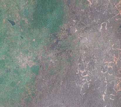
F.1) Low resolution (i.e. of 30 m as of old days’ Landsat) is not very useful for land use mapping and land use planning, because you can identify only very large objects such as water bodies, forests etc
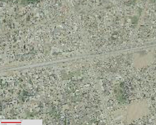
A resolution of 3-10 m can help to see objects such as large buildings, sufficient for small-scale land use mapping:
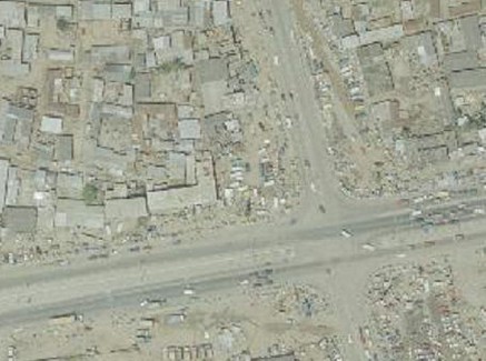
Only a resolution of 1 m or better can show sufficient detail to see all objects necessary for land use mapping for structure plans (see Chapter 7.2.
See also Chapter 7.3.1 and Annex 2.2.2 (3rd para) for resolution requirements of LUPMIS, to come up with a land use plan accuracy of +/- 10 m:
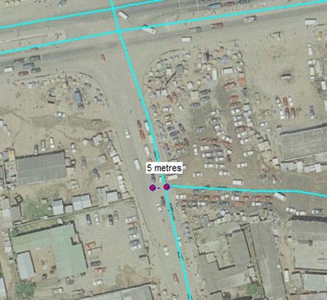
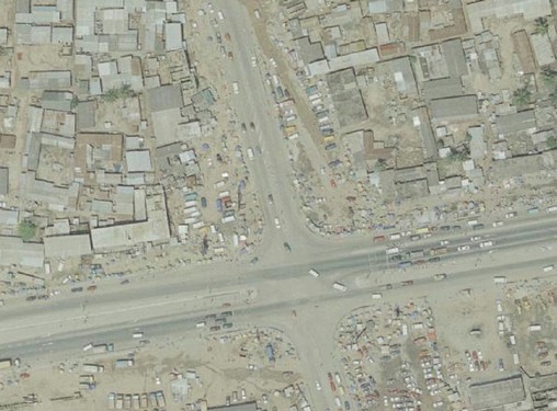
A resolution of 20-40 cm or better will be that detailed, that even mapping - and surveying - for local planning can be carried out (see Chapter 7.3):
- - - - -
F.2) The horizontal accuracy determines how precise is the location (thus, the coordinates) against the coordinate system of the base map or of the GPS. For land use mapping and land use planning, an error of +/- 3 m is acceptable as the difference between the georeferenced image and the 'true' coordinates. Geodetic and cadastral surveys require higher accuracy, e.g. of sub-meter level.
This can be tested by comparing features on the ground with high-accuracy GPS against the image.