6.2 Styles and Symbols - LUPMISManual
Main menu:
6.2 Styles and Symbols
Level of expertise required for this Chapter: Intermediate; general Map Maker training
6.2.1 Background
The general process for the layout and print is: Style --> Legend --> 'Furniture' --> Print
‘Styles’ handle the presentation of polygons, lines and points, i.e. the appearance of mapping features in Map Maker. Style sets are organized in style libraries. They define the colours or hatching:
A) Polygons:
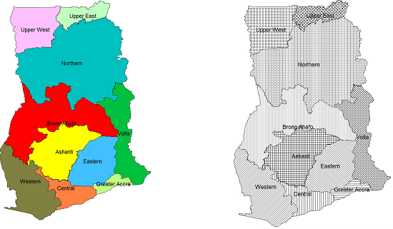
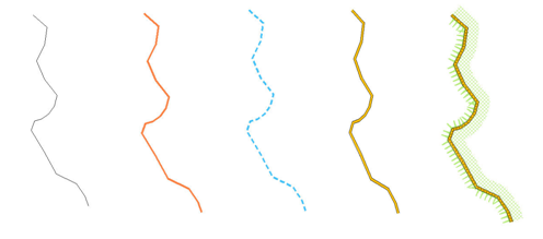
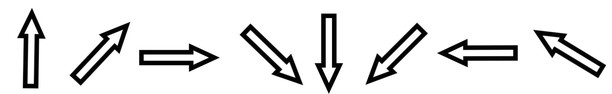
B) Lines:
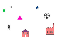
C) Points:
There are three different types of style libraries:
A) Default style set: Appears, when you load Map Maker.
Note 1: See Annex 1.1.3 step 8 for manual configuration.
B) Theme-specific style sets: For example, for road, altitude etc.
Note 2: All pre-defined libraries of LUPMIS (extension STL) are stored in folder C:\Map Maker\Configuration\Style library, and have self-explanatory names. See Annex 5 , also Note 1 above.
C) Project style set: With all changes of the default style set, saved with the project (see Note 3 of Chapter 1.6, and Chapter 6.6.1).
6.2.2 Source of Style Libraries
Style libraries will be provided by TCPD-HQ / LUPMIS, as the display of mapping features should be standardized for TCPD activities.
You can define a new style library through:
Main menu > File > System set up > Styles library > Set up window: Styles library > New style set > Name new library style set window: Enter new name > OK > Proceed with the editing, as explained below > OK
A style set received by copying the file to your computer, has be to imported to your Map Maker by:
Main menu > File > System set up > Styles library > Set up window: (if there is an old one with the same name, this has to be removed first. Then:) Import style set > Select folder and file name > OK
6.2.3 Editing of Style Libraries
If you have a style set, but want to edit it, for example want to change the colour, the edge of the polygon, the line width, the symbol etc, you have to enter the style editor:
Main menu > File > System set up > Styles library > Set up window: Styles library > Select library style set in left column > Edit > Style set editor window
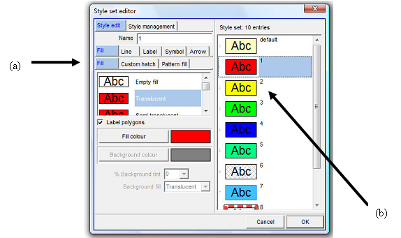
The right column shows the styles with their polygon, line, point and text definition. You can change each of these features individually by selecting (a) the feature and (b) the style number.
To add more units to the existing style set (upto 256): In the Style set editor window move to the unit, after which you want to add new styles (for example, the last one) > Style management > Edit set > Create new styles > Add new styles window: Number of new styles > OK
There is a wide range of options to modify the style, such as change of name, colour, transparency, appearance of label, width of line, appearance of line, point symbol etc. Most of these are self-explanatory, and can be accessed through the Style set editor. Also, created styles can be copied (through Style management).
6.2.4 Selection of Style Library for Display of Individual Layers
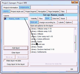
Each time you load a layer and want to apply the defined style, you have to assign the layer to the style: After having loaded the layer (‘Add layer’): Main menu > Project manager window: Components > Layers > Style > Style set > Select Library
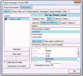
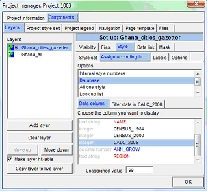
If specific cases, you might not refer to the style (in your DRA file), but a data column in your attached database (DBF file): After having loaded the layer (‘Add layer’): Main menu > Project manager window: Components > Layers > Style > Style set > Define library > Assign according to … > Database > Data column > Select TYPE or similar field, which contains the code for the style set > OK
6.2.5 Project Library
If you like to change the style only for the current map, you can do so by changing the style of the current project: only (so-called ‘project style set’): Right-mouse > Project manager > Project manager window: Components > Project style set > Continue with the style editor, as explained above > OK
This particular style will be lost, unless you save the entire project (Main menu > File > Save Project).
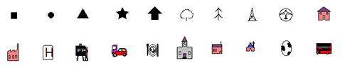
6.2.6 Creation of New Point Symbols
In exceptional cases you might have to create new symbols as point styles:
- 1. Symbol set: If LUPMIS is installed, just use the LUPMIS symbol set. Otherwise, you have to create a new symbol set: Main menu > File > System set up > Edit symbols sets > Set up window: New symbol set > Name new symbol set window: Enter new name > OK
- 2a. If you dont require transparency in your symbol, you can call a graphics BMP file (preferably size of 512 x 512) by Project manager > Add layer > Files of type: BMP > Select graphics file > OK
There is an alternative way to import a BMP file:
You have to pre-process in Paint Shop by reducing color depth to 2: Image > Decrease color depth > 2 color palette. If you want to change the color: Image > Palette > Edit palette > Click on color to be changed.
Import this BMP file in Map Maker: Project manager > Project manager window: Project information > Extent > Untick: With background color > Components > Layers > Add layer > Files of type: BMP > Select graphics file > OK > Style > Untick: Zoom out use gray scale > Tick: Opaque (this is only possible, if color depth of 2) > Ok > You might have to zoom in a little bit that symbols covers main part of screen > Main menu > File > Save screen image > as symbol > Select symbol set (e.g. Logos1) > Select symbol. The background of the symbol will then be transparent, because no background color was selected.
- 2b. In most cases, you want the symbol to be transparent. You have to draw it with the editing tools of Map Maker: Main menu > File > Clear > Button tools: Polygon and draw polygons, similarly also lines and points > You might have to choose or modify the project style set to get the correct colours > OK
- 3. Once the symbol appears nicely in your Map Maker (covering some 90 % of the Map Maker window), capture it into the symbol set: Main menu > File > Save screen image > as symbol > Choose or name symbol set: Select the symbol set from step 1 (e.g. LUPMIS) > OK > Choose or name symbol: Enter name for new symbol > OK
If you want to delete, you have to delete both in Set up window (Main menu > File > System set up > Edit symbols sets > Set up window: Delete symbol set) and the SYB file in Windows Explorer in folder C:\Map Maker.
Note 1: If the symbol appears to be very small, increase its size at the project manager window: Project style set > Symbol > Select style number (at right) > Increase size (at bottom left) > OK
Note 2: Symbol information is saved in the folder with the symbol set name in C:\Map Maker\Configuration\symbols and in the SYB file in C:\Map Maker\Configuration.
- - - - -
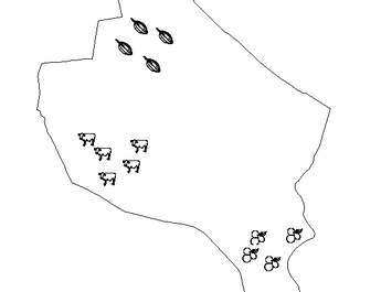
An ‘Agric’ symbol set has been created for the project to symbolize agricultural patterns and potential on the maps. It can be requested from LUPMIS/TCPD-HQ (see also Annex 1.1.1 for installation and Annex 11 for distribution CD).
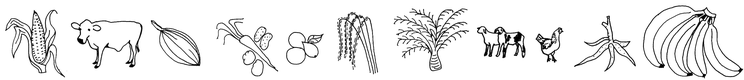
and:
With these kinds of symbol sets, you can create indicative distribution maps, as below:
6.2.7 Bands for Graded Features
If you have quantitative data in a thematic map, you can also use the option to assign graded colours or symbols based on the numeric data, instead of using styles.
Right-mouse > Project manager > Project manager window: Layer > Select layer > Style > Assign according to … > Database >
Data column > Select column containing the data >
Filter data in …. > Either: New filter (> Select folder > Write new file name > Save >) or: Choose filter > Select folder and file > Edit filter > )
If you have points to display according to their value:
Data bands window: Filter > Specify how many bands (classes) you want > Tick both ‘Use symbol colours and size rather than styles’ and ‘Graded colours and size’ >
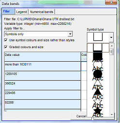
Under ‘Symbol type’ a listing should appear. (If it does not appear, untick these two options, and re-tick again) > Select the symbol > OK >
Still in Data bands window: Numerical bands > You can specify the quantitative width of each band by clicking and dragging the drag button on each threshold > OK > OK
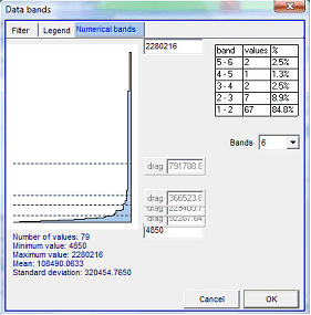
Note: The definition of this grading scale has been saved in a ‘filter’ (txt file), not in a style legend.
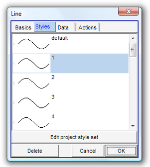
6.2.8 Change Current (Project) Style
If you are in live layer, the project style is applied, not a specific style. You are able to change the project style set: In live layer mode: Edit-tool (at toolbar left) > Click on any polygon > Polygon window: Styles > Edit project style set > Style set editor window: Style management > Import style set and overwrite > Choose style set window: Select style set > OK > OK > OK
6.2.9 Load Data to Style Field
You can assign style numbers to units:
A) Either, individually in live layer mode by the Edit-tool (at toolbar left) > Select the unit > Styles > Select the style (class) > OK
B) Or, by filtering many units and make an assignment for all of the selected, through: Copy layer to live layer > Main menu > Edit > Show Selection Manager > Selection Manager window: Find objects by criteria > Find > Search by criteria window: Double-click on the field under Terms and complete search condition under Criteria Statement > The green ‘valid’ tick should appear > OK
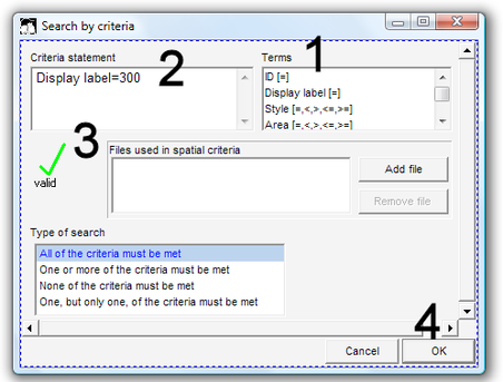
Selection Manager window: Listing all selected units > Actions > Basic operations > Set all objects to one style > Choose style window: Select style number > OK > X
Don’t forget to save at the end.